DIANA 75 TEARDOWN & OVERHAUL DETAILS
with trigger diagram
This can be the hardest part of the whole affair. At least in my case it was.
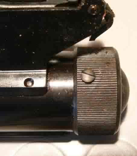
The end cap is screwed onto the receiver. Then the factory drills & taps a hole in the side to “clock” the end cap.
The end cap is not under preload. But it does contain a washer/shim combo that is set at the factory. The idea is to take the load off the idler gears at full extension of the forward piston. The rear “seal” is not a seal but a buffer that impacts this washer/shim in the end cap. A process that is aided by the pellet causing backpressure.
The cap has 2 holes that a pin spanner can be inserted into. If your gun has been serviced previously it is likely you can use this tool or a strap wrench to get it loose after taking the set screw out.
Mine required more “persuasion” (see above link to the post).
Once the end cap is off the rearward piston is exposed. As the rear piston has a hole in the center as it is really just a counter weight. Use a spring compressor on a secured gun & a tapered cone to fit in the hole in the rear piston. Then VERY slightly compress the piston. just barely make it move. Then the “hubcaps” can be taken off safely. These are idler rollers threaded into the chamber tubes with very fine threads. these are easily damaged of course. The factory also provides pin holes here but once again more effort than they can supply is usually needed.
Unscrew them less than 2 turns. If they do not turn easily adjust the tension on the rear piston with the spring compressor till they turn freely. Also at this time its good to note the amount of clearance at the rear piston to the face of the tube. This is the exact amount you want to use when you re-install the pistons so please mark it or not it somehow.
Also, match mark the parts as needed. Up, down-teeth contact points etc..
Once the hubcaps are off this is what you see…
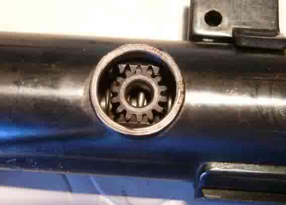
Don’t freak out. They are just idlers & pull right out. Remove one side 1st then you can rotate a piston to one side slightly to free the other. That’s usually not needed.
Now release tension on the compressor & the springs will drive the piston backward. Use your brains & try & keep it from flying Ok?
Now you have the guts all exposed & ready for whatever cleaning, sealing etc.. you need.
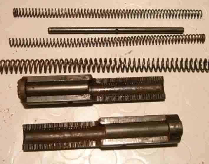
Here’s a side view of the pistons nicely laid in place with the springs etc…
Aligning the rear sleeve & the springs etc… while inserting the rear piston is a job for a octopus. I used a small screwdriver through the hubcap ports to keep it in line while compressing it.
After the rear piston is pushed back in exactly as much as you had marked previously your very close. With luck you can inbstall the idler gears & then the hubcaps. Adjust tension as needed to prevent binding & certain thread damage. If the caps don’t turn free it’s not right period.
The rear piston can be pushed too far forward & go back together. The result will be a gun that refuses to cock. Always check the amount of end clearance. Another clue the gears are set correct is when viewed through the hubcap ports you can just see both ends of the gear racks on the front & rear piston-Evenly spaced.
After you snug the hubcaps lightly it is time to release the compressor & re-install the end cap.
Lightly grease the threads & make sure the shim/washer are correctly placed. remember this acts as a stop for the rear piston buffer.
Thread it on until it is exactly aligned with the set screw & re-install same.
Breath a sigh of relief-You earned it!
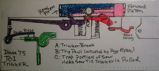
Here’s a brief look at the workings of the T01 trigger…
IMG_0030.JPG
I know my kid could have done better but hey! it’s for educational purposes!!!
Anyhow, the “girder” looking thingy was omitted in this view. It is a block for the trigger & essential to function but you can’t see a dang thing with it there.
First, with an empty trigger cage install the trigger block girder from the muzzle end. The screw head fits under the trigger eventually but for now it has to be placed as far rearward as possible to install the trip pawl (purple) next.
Both these pieces have pawls that interact with the pistons so after they are in the cage they must be properly located. Next install the sear (red) & the 2 springs for the sear & the trip pawl. Then install the blade spring just behind the sear as pictured (orange). This is for the safety pawl catch.
Please refer to the factory diagram for the itty bitty parts but it is all pretty basic after that.
The “girder” is connected to the forward ratchet. The lever forward of the ratchet is pushed by a screw in the forward reciever. When it is closed it pushes the trigger block girder back.
There is also an adjustment for the safety catch just behind the sear. It should also “lift” when the breach is closed. Mine was at the rear 1/3 position on the slot when adjusted correctly.
Hope this helps others prevent some of the problems I had & keep these GORGEOUS old guns running strong.
Cheers!
Carl Rettig, Basic Airgun Tunes