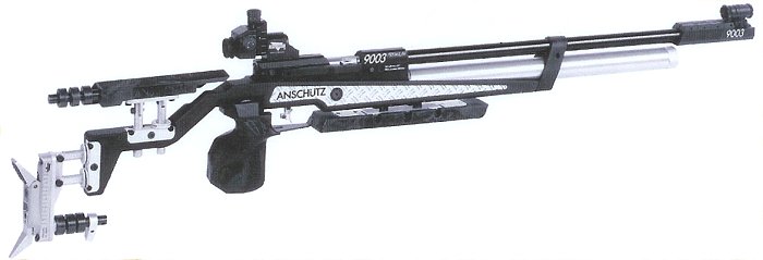
ANSCHUTZ 9003
5065 Trigger Adjustments
Trigger Weight
Turn screw F2 clockwise to increase weight. Range is 30g to 150g.
First Stage Weight (only for 2-stage triggers)
Turn screw F1 clockwise to increase first stage weight.
Trigger weight and first stage weight are interrelated mechanically. If one of them is changed there will always be a corresponding change in the other.
First Stage Travel (only for 2-stage triggers)
Turn screw L clockwise to shorten travel.
Trigger Stop
Turn screw T clockwise to shorten after-travel.
Setting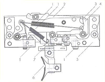 Single or 2-Stage Trigger
To set single stage trigger, turn screw L clockwise until the first stage movement has been eliminated.
Warning: Single stage triggers are very sensitive and must be used with special care. In case of a minimum trigger weight there is increased risk of an accidental discharge.
To set a 2-stage trigger, turn screw L counter-clockwise until the desired first stage travel has been achieved.
Basic Adjustment of the Trigger
With this procedure all adjustments of the trigger are zeroed. From this zero position it is possible to adjust the trigger to your individual requirements:
– Remove the barreled action from the stock.
– Adjust set screw T in a way that the screw head lies flush with the external surface of the trigger housing (5).
– Adjust set screw L in a way that the trigger support (7) is horizontal.
– Cock the barreled action.
– Adjust the trigger via the referred screws to your individual requirements.
Trigger Blade
Loosen clamping screws as desired. The trigger blade can be moved in the longitudinal guide, can be tilted laterally and can be adjusted in height. The trigger blade can also be pulled out completely and turned by 180 degrees. The longer part of the trigger blade is now directed downwards. The trigger blade holder is asymmetric and acn be mounted in opposite direction. The lateral trigger blade can be varied this way.
Attention: The screws A, B and C are sealed by the factory and must not be adjusted otherwise.
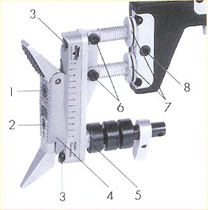
Stock Adjustments
| Fore end can be adjusted: – in height via screw #1 – horizontally via screw #2 – in length via screw #3. |
 |
| Each adjustment is carried out by separate clamping devices. 1. Upper slope at shoulder. 2. Height and angle adjustment of butt plate. 3. Horizontal adjustment of butt plate. 4.Height adjustment of hook. 5. Thread for weight carrier. 6. Vertical adjustment of butt plate. 7. Stop nut. 8. Length adjustment of butt plate. |
 |
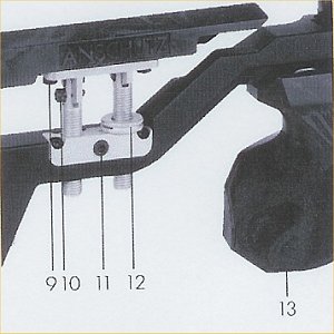
| 9. Horizontal adjustment cheek piece. 10. Slope cheek piece. 11. Height adjustment of cheek piece. 12. Stop nut. 13. Adjustment of pistol grip. The grip can be turned, pushed and tilted in all directions. |
 |
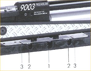
To Change the Cocking Lever
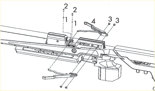
From the right to the left side or vice-versa:
– Pull the safety disc (1) off the bolt.
– Remove the bolt (2).
– Loosen the screws (3).
– Remove the complete cocking lever unit (4) and install on the opposite side in reversed sequence.
Cutaway of the 8002 action.