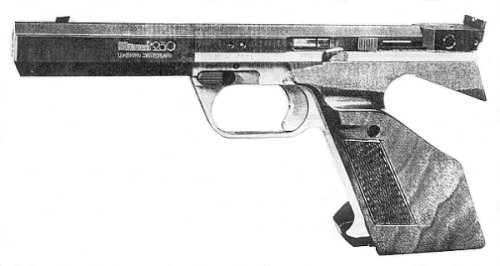
HAMMERLI 230
Sight Adjustments
Elevation: Clockwise down.
Windage: Clockwise right.
1 click = 10mm @ 25m.
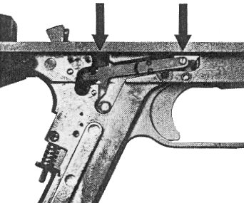
Trigger Adjustments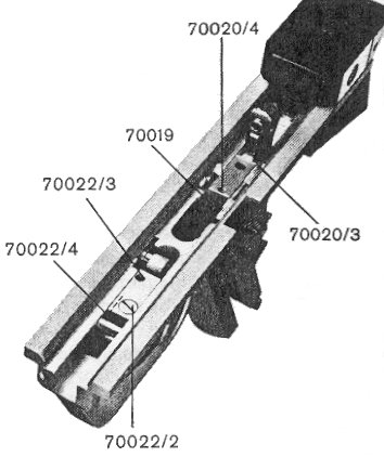
First Stage Travel (Take-up): Loosen set screw 70022/4 with allen key. Turn screw 70022/3 anticlockwise to increase takeup. Note. If the takeup screw is turned too far clockwise (to shorten takeup) the trigger bar notch cannot engage the trigger sear cam. Cock hammer and check engagement. When adjusted to satisfaction, tighten set screw 70022/4.
Trigger Weight: Loosen set screw 70020/4 with screwdriver. Turning screw 70019 clockwise will increase trigger weight. Minimum trigger weight is 260 grams. After adjusting, retighten set screw 70020/4.
Sear Engagement: Turn screw 70020/3 clockwise to reduce engagement.
Important note: Hammer and sear notches must never be ground or stoned.
Trigger Stop: Turn screw 70021/4 clockwise to reduce overtravel.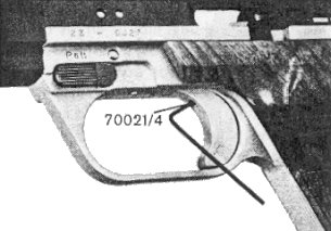
Caution! Too short a backlash can cause gun to maxim.
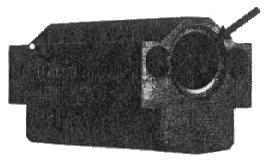
Stripping
| Check pistol is unloaded and remove magazine. Turn the locking lever by 180 degrees to the rear. | 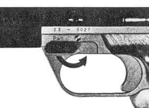
|
| Grab the pistol at the barrel. Receiver and barrel can now be drawn forward and be tilted for disassembly. | 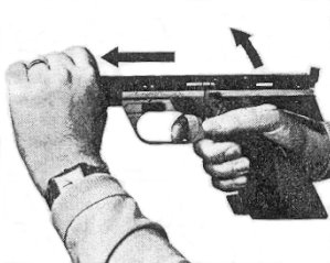
|
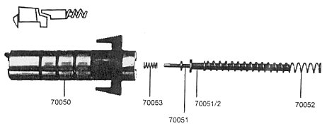
| Barrel/receiver unit must be held vertically with the muzzle pointing to the ground in order to prevent the bolt, recoil spring, firing pin, firing pin spring and firing pin guide from falling out. These parts are all placed in the receiver and bolt respectively without any fixation. Care must therefore be taken not to lose any parts. |
|
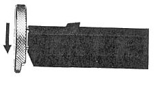
| Remove grips. Remove muzzle nut by turning it with the special tool. |
|
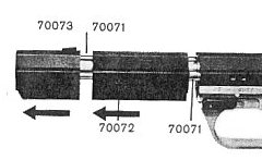
| The gas-diversion piece can now be removed by pulling it to the front. Should it stick on the barrel, clamp the gas-diversion piece into a vice and withdraw the pistol. The intermediary sleeve made of light alloy can now also be removed. Before reassembly the outside of the barrel and the two gas tubes should be lightly lubricated using a high quality gun oil. But the inside of the gas tubes should be left dry. |
|
| For cleaning, mount 6mm drill supplied into opposite side of special tool. Then clean the gas-diversion piece by hand drilling the two ducts from the rear until the drill tip is well visible through the gas escape holes on top. Mount 4mm drill supplied into special tool and clean the two gas tubes 70071. Hand drill carefully until the drill tip reaches the end of the tubes. Residue is thus loosened and can be tipped out. DO NOT use the 4mm drill to clean out the top holes. If they are clogged a small screwdriver can be used to loosen it until it falls out. If necessary the ducts in the intermediary piece 70072 (illustrated) can also be cleaned with the 6mm drill. On reassembling care should be taken that this piece is placed correctly with the ring groove facing the receiver. |
|
| Lubricate these two areas with a non-resinous oil (sewing machine, vaseline or spindle): a. Disconnector cam/trigger bar b. Turning-point of the trigger bar. |
|
Locking Lever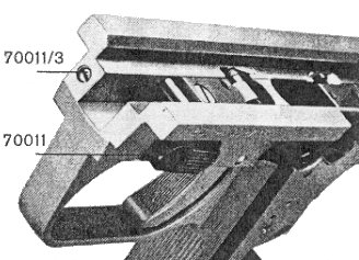
The spring tension catch on the locking lever 70011 can after long use be tightened by turning the screw 70011/3, which presses on the spring and the small catch-ball.