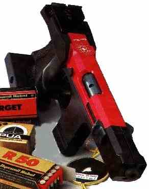
HAMMERLI SP20
Rear Sight Adjustments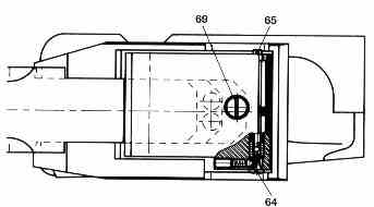
Clockwise down (screw 69). 1 click = 100 @ 25m.
Clockwise left (screw 64). 1 click = 8mm @ 25m.
Width of rear sight aperture adjusted by screw 65. Clockwise to widen opening.
Front Sight Adjustments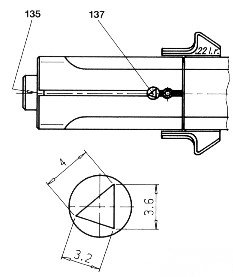
The front sight has three positions to give apparent widths of 3.2, 3.6 or 4.0mm. The sight may be turned by first loosening screw 135 with socket spanner (SW 1.5), then tightened in any of the three positions.
The following sights are available as optional spares:
Part # 1.333.160 – 3.8/4.4/4.7mm
Part # 1.333.150 – 2.4/2.8/3.2mm
Part # 1.333.170 – 3.2/3.6/4.0mm – extra high
Trigger Adjustments
The following are instructions lifted straight from the manual.
Initial Setting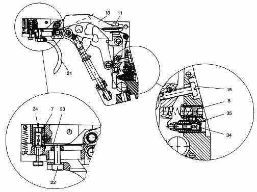
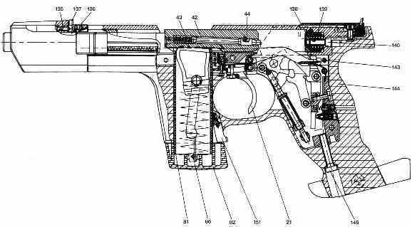
Rotate trigger stop #24 anticlockwise with allen key SW 1.5 up to the stop.
Rotate let-off screw #34 clockwise with allen key SW 1.5 (through approx 2 turns or up to the stop).
Rotate threaded bush #35 anticlockwise with blade 2 of Combitool through approx 1 – 1.5 turns.
Rotate trigger stop screw #24 clockwise with allen key SW 1.5 through 5 turns.
Turn screw #8 anticlockwise with allen key SW 2.5 up to the stop.
Cock the hammer. Slowly rotate screw #15 clockwise with blade 1 of Combitool until the hammer drops and then rotate the screw anticlockwise through 1 1/4 turns.
Cock the hammer. The hammer bar #18 must register with #11. If not, turn threaded bush #7 anticlockwise until #18 engages. If there is no backlash between #18 and #11, the threaded bush must be turned clockwise until there is minimum 0.05mm or maximum 0.2mm available.
Let-off position: Rotate #35 clockwise with Combitool blade 2 until a let-off point is felt. Cock the hammer, draw the trigger tongue to the let-off position and hold. Slowly turn #35 anticlockwise until the hammer drops. Now rotate minimum 1/8 to maximum 1/4 turn clockwise. Let-off force must increase cleanly and finally break dryly. At this point, apply a small quantity of Molycote to the notches.
Take-up weight: Rotate screw #8 clockwise through 1/2 turn with allen key SW 2.5. Turn screw #34 anticlockwise with allen key SW 1.5 until the trigger pull reaches 1000g (check with weight or scales). To increase from 1000g to 1360g see below.
Trigger stop: Cock the hammer, draw the trigger tongue to the let-off position and hold. Turn screw #24 anticlockwise until the hammer can no longer be dropped. Now slowly turn screw #24 clockwise until the hammer trips and continue turning clockwise 1/4 – 1/2 turn.
Is the trigger now okay? If so, stop here. If not, go back to the beginning.
Trigger Slack Position
If the trigger slack is no longer perceptible or if a longer slack path is required:
Rotate screw #34 clockwise through 2 turns with allen key SW 1.5.
Rotate threaded bush #35 clockwise through 1/4 turn with blade 2 of the Combitool. Adjust range maximum plus or minus 1 turn.
Rotate screw #34 anticlockwise through 2 turns with allen key SW 1.5.
Can let-off point now be clearly felt? If so, check trigger weight and stop. If not, start again.
Trigger Slack Path
Path between rest position of trigger piece and trigger slack position. Adjustment is made with 3 mutually influencing screws. The screws must therefore always be adjusted in sequence, taking note of the relationship (see diagram).
Rotate screw #24 clockwise through 2 turns with allen key SW 1.5.
Rotate screw #15 clockwise through 1/4 turn with blade 1 of Combitool.
Rotate screw #7 clockwise through 1/3 turn with blade 3 of Combitool.
Cock the hammer. Trigger bar #18 must register with #11. If not, turn threaded bush #7 anticlockwise until #18 engages. If there is backlash between #18 and #11, turn the threaded bush clockwise until there is a minimum 0.05mm or maximum 0.2mm available. To check the setting, cock and drop the hammer several times.
Reset trigger stop as per instructions above.
If take-up length is now correct, stop here. If not, start again.
Trigger Slack Force
Screw #8. The trigger slack force is increased by tightening in the clockwise direction. Grub screw (SW 2.5). Increase of weight per revolution approx 150g.
Trigger Slack Weight
Screw #34. By tightening clockwise with grub screw (SW 1.5mm). Increase of weight per revolution approx 350g.
Adjusting from Standard/Sport to Centre Fire
There are three possibilities for adjustment from 1000g to 1360g:
Increase take-up weight only.
Rotate screw #8 through 2 1/2 turns clockwise. Only take-up weight increases. The screw is accessible from the outside through the hole in the rear of the grips. Allen key SW 2.5.
Increase let-off weight only.
Rotate screw #34 through 1 turn clockwise with allen key SW 1.5. This increases let-off weight only.
Increase take-up and let-off weights.
Rotate screw #8 through 1 1/4 – 1 1/2 turns clockwise with allen key SW 2.5. Rotate screw #34 a turn clockwise with allen key SW 1.5. Both take-up and let-off weights are increased.
Buffer
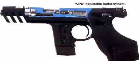 The Hammerli SP20 is fitted with an adjustable buffer. The recoil and sensitivity in the hand can be set individually with screw #140.
Basic setting of buffer:
Turn screw #140 clockwise fully to the stop, then turn back approx 2 1/2 revolutions.
Recommendation:
Soft ammunition – screw in 1 revolution clockwise from basic position.
Hard ammunition – release 1 revolution counter-clockwise from basic position.
Please ensure in all cases, however, that the buffer can still be moved.
Stripping
Check pistol is safe and hold slide open with slide catch.
Release socket-head screws at muzzle (allen key SW 3).
Withdraw barrel holder with barrel forwards.
Release slide catch and remove slide forwards.
Release screw #149 with allen key SW 3.
Release grip frame from receiver casing.
Push out cylindrical pin (#143) between receiver casing and trigger unit and withdraw trigger from rear.