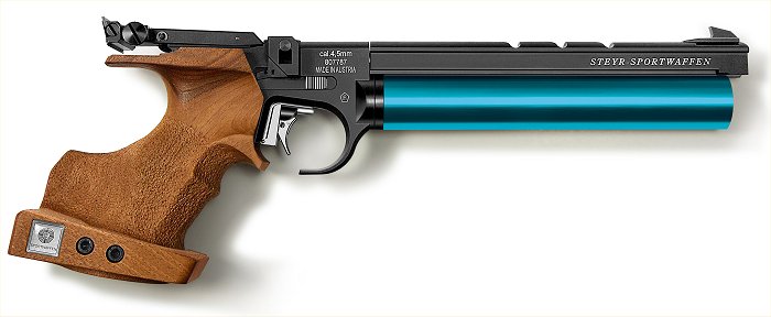
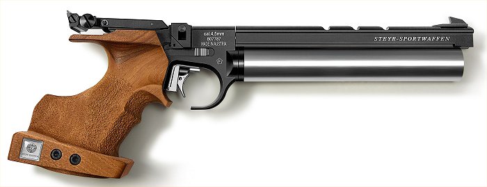
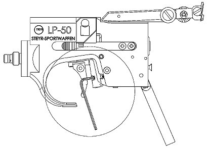
STEYR LP50
Sight Adjustments
Elevation: Clockwise down (left hand knob).
Windage: Clockwise left (right hand knob).
1 click = 1.2mm @ 10m
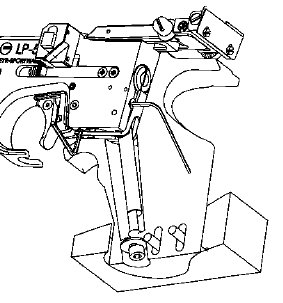
Rear Sight Adjustment
Turning the screws #79 or 80, the rear sight gap can be adjusted from 1.5 mm to 4.5 mm.
The depth of the rear sight is adjustable from 1.5 mm to 3.2 mm. Loosen the cover plate screws, move into desired position and then retighten screws.
Relocate Rear Sight (altering sight radius)
Loosing screw #106, slide sight carrier to the desired position and tighten screw.
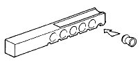
Loading
| Filling the Magazine Place pellets one after the other, as shown, into the magazine chambers provided in such a way that the pellet is completely flush with the magazine (skirts do not protrude). |
 |
| Cock the action by pushing the left and right slides simultaneously backward with thumb and index finger. The magazine may be inserted only when the pistol is cocked. | 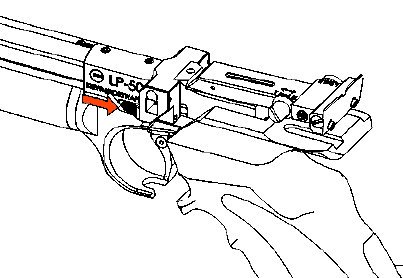 |
| It is impossible to insert the magazine the wrong way because the recess on the magazine and the spring sleeve in the magazine housing must match. | 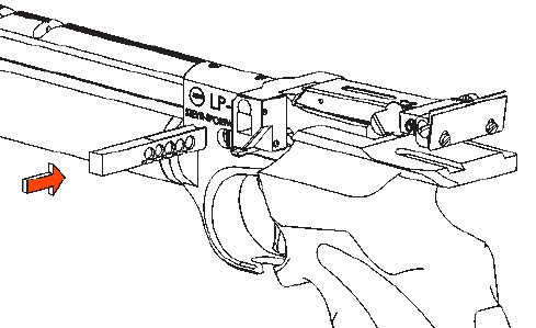 |
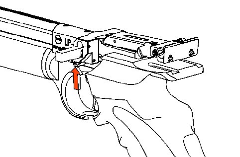
| Removing the Magazine (Unloading) After five shots are fired the magazine is empty. The action is still cocked. If the magazine catch located at the bottom left of the magazine tube is lifted, the magazine can be removed. Should the trigger have been pulled a sixth time the system has to be cocked again in order to be able to remove the magazine. The magazine may also be removed without emptying it. When pressing the magazine catch, ensure the magazine, which is under spring pressure, does not fly out. |
 |
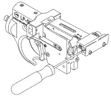
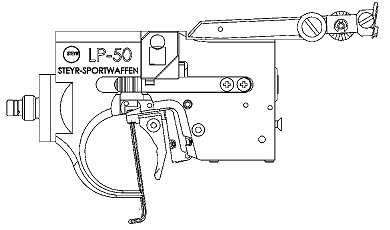
Trigger Adjustments
| Trigger Blade Loosen countersunk screw. The trigger blade may then be moved either to the left or to the right and moved in a longitudinal direction. |
 |
| Trigger Stop Turning the screw clockwise shortens the “aftertravel” of the trigger blade after shot release. Turning the screw anticlockwise lengthens the “aftertravel” after shot release. |
 |
| Trigger Weight Turning the screw anticlockwise reduces the trigger pull force. Turning the screw clockwise increases the trigger pull force. |
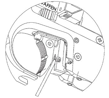 |
| First Stage Travel Turning the screw clockwise reduces the dead travel. Turning the screw anticlockwise increases the dead travel. Note: the trigger must have some takeup – if eliminated entirely the trigger may not reset. |
 |
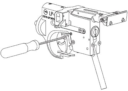
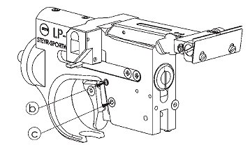
| Swapping the Trigger Assembly Remove grip by loosening the socket head screw on bottom side of grip. Remove fastening screw. Remove clamping screw. Remove complete trigger assembly from casing. With the slides retracted insert trigger assembly into the pistol casing and place it against the stop up to the front of the casing. Fasten clamping and fastening screw. |
 |
Grip Adjustment
The grip is adjustable and pivotable to the frame in all directions and may be widely adapted to the shooters stance. For this purpose the grip has to be removed. Adjustment is achieved by means of the screws located at the bottom and the rear of the casing.
PLEASE NOTE! The two countersunk screws on the rear of the casing must always protrude at least 2.5 mm, to assure the velocity screw is clear of the grip.