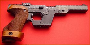
WALTHER GSP
Sight Adjustments
Clockwise down. This makes perfect sense when you realise that “bei” means “if”.
Clockwise left.
1 click = 7mm @ 25m for elevation.
1 click = 5mm @ 25m for windage.
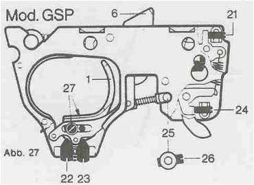
Trigger Adjustment (Early Model Trigger)
Basic Setting
The following are the factory instructions for a basic setup using the first stage travel adjustment screw.
Cock the hammer (6). If it does not engage, turn screw 21 counter clockwise until the hammer stays back. Now slowly turn screw 21 clockwise until the hammer disengages, then turn same screw back again about 1/4 turn (counter clockwise).
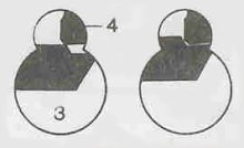
Turn screw 22 clockwise until the trigger bar (3) comes to lie beneath the trigger pawl (4) when the hammer is cocked (left view). Press the trigger (1) backwards and at the same time turn screw 22 slowly counter clockwise until the trigger bar (3) with its detent rests at the trigger pawl (4) (right view). To check, push the hammer (6) downward and then let it glide slowly back; the trigger bar (3) must now drop in practically free from any play in front of the trigger pawl (4).
Adjusting Trigger Stop
Cock the hammer (6). Turn screw 23 clockwise until the hammer (6) does not release when the trigger is pulled. Press trigger fully back and at the same time turn screw 23 slowly counter clockwise until the hammer disengages. To obtain the desired trigger slack turn screw 23 counter clockwise a further 1/8 to 1/4 of a turn.
Trigger Weight
Screw 24. Clockwise to increase weight.
Trigger Shoe Position
Loosen screws 27 to adjust length of pull.
Stripping Instructions
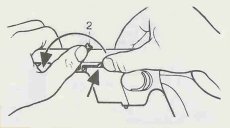
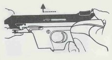
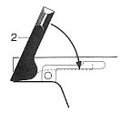
| Remove the magazine. Check pistol is unloaded. Let slide forward and uncock the pistol. Push the locking spring on the slide locking lever (2) in and turn the latter fully forward. |
 |
| Push the upper part (barrel with slide) forward by about 7mm and lift upward. The slide lock must lie horizontally. DO NOT USE FORCE. Caution: Do NOT put the upper down on its top side! |
 |
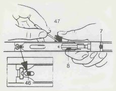
| Loosen the barrel locking screw (7) with the Allen key until the locking pin for the cocking piece (see arrow) coincides with the hole in the side casing. | 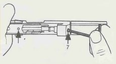 |
| Push the spring-loaded pin inward, at the same time pushing the cocking knob (47) out (see arrow). | 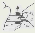 |
| Open the hinged ejector (8). Loosen the barrel locking screw (7) until the barrel can be withdrawn, then pull the breech block out of the slide casing. | 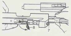 |
| Turn the locking screw (3) 180 degrees, then grip the trigger unit by the decocked hammer and pull the unit upwards and out. (The trigger unit is locked in place when the mark on the locking screw points in the direction of the muzzle, ie forward). | 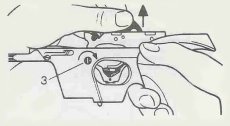 |
| To reassemble: Do not use force! Re-insert the breech block in the slide casing. Mount the barrel and with the barrel holding screw (7) down firmly, then push in the cocking grip (47) and turn the ejector back (8). Push the trigger unit firmly into the frame and lock with the locking screw (3). The point on the locking pin must then stand in line with the barrel. |
 |
| Now place the slide casing on the frame at a spot about 7mm forward of the “closed” position, push fully backwards, then turn the slide locking lever (2) fully home to the rear. | 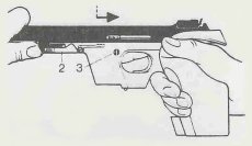 |
Readjusting Slide Locking Lever
The slide locking lever firmly connects the frame with the slide casing. If the clamping strength weakens, readjust the slide locking lever in the following manner:
| Turn the slide locking lever (2) forward. Remove the screw (1) and lift the star spring (5) off and out. Screw the slide locking lever out by about two and a half turns. | 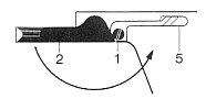 |
| Hold the nut (3) on the opposite side firmly in position while doing so. | 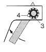 |
| Push the slide locking lever (2) against the pistol. This causes the nut (3) to be pushed clear of the locking pin (4) so the nut acn then be adjusted. To increase the tension, turn clockwise; to decrease, turn anti clockwise. | 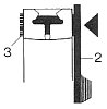 |
| Push the nut (3) in again and turn the slide locking lever (2) back into the “locked” position. A certain amount of gripping pressure must be perceptible while the lever is being pushed home through the final portion of its travel. Check to ensure that the slide casing sits firmly on the frame, then replace screw (1) and spring (5). |
 |